Wo ein Wille ist, da ist auch ein Weg, aber wo Jörg hin will, ist noch lange keine Strasse. - Ulla T. et al. aus Münster
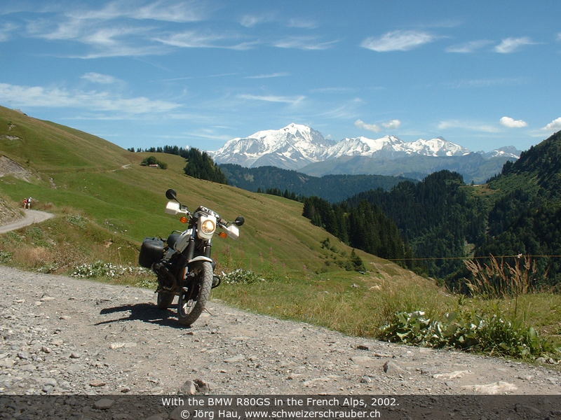
For me, the BMW R80 GS is a wonderful bike. Of course there are other bikes that are "wonderful", but there are some particular reasons why I simply like my good old GS. It is a fairly uncomplicated, easy-to handle machine. I like its decent touch of "brute force" when you open the throttle at 1500 rpm. I like the possibility to load 220 kg onto its back and to go wherever you want. Somebody once said "where you can go with a horse, you can also go with the GS". Indeed it was usually not the GS that reached its limits ...
I bought my GS in 1990, brandnew and it was the fulfilment of a long dream for me. Since then we have gone more than 205'000 km together. I have to say that the GS was not the bike with the least problems I ever had (that was probably my Suzuki GSX 400E), but the GS was never "on strike". Here's a little history of the things that I have noted and/or done over the years - maybe it can help you.
The usual disclaimer: These are things that I did on my own R80GS, which is the 1990 model as it was delivered for the German market. Most of it should also be applicable for the R100GS and the R100R. I did this with my own bike and on my own risk, so if you repeat this with your bike, you do it obviously on your own risk.
Hepco carrier with Hepco "Junior" 40 l bags. The view from behind is amazing as the bike is really laaarge with those bags, but they are robust and waterproof. The Hepco carrier is known for its stability: It is soldered from tubular steel and has solid reinforcements down to the passenger footpegs and under the license plate. The carrier cost about 230 DM back in 1990, the bags not quite twice as much.
After more than 10 years and over 100 Mm some signs of wear start to show up - but only on the bags, not on the mounting frame. The mounting brackets started to come loose, which was simply fixed by replacing the worn-out rivets with M4 bolts and self-securing nuts. Another little defect is that a few "corners" of the plastic had broken out on the back of the bags (where they slip onto the mounting frame), allowing water to enter the luggage. Once these small holes were located - pour a few litres of water into the bags and look where it leaks out -, this could also be fixed easily with some drops of two-component glue (or polyester resin, if you prefer that).
At 119'000 km, I had to replace one of the mounting brackets because the lock could not be locked anymore (broken lid; left circle in the photo ... it was the lock of the other bag, not the one shown here ;-). A replacement lock was readily available through the local Hepco/Becker reseller in Switzerland and cost about 57 CHF (incl. shipping; spring 2003). At that time, the lock of the other bag is showing a small fissure (right circle in the photo) which broke in spring 2004. I could use the parts from the other lock to fix this.
Early 2006 I had the occasion to obtain two almost unused bags of the same type, so I sold the "old" ones. The newer generation is improved in many aspects but the locks still have a tendency to develop backlash over time, which is unfortunately a self-amplified process ... the "play" will increase over time.
In the frame of the HPN modifications of summer 2017, I completely disassembled the bike and had the frame powder coated, including the luggage carrier. To reduce backlash and provide a better fit for the bags, I added a layer of rubber that was simply cut from old bicycle tyre tubes. They are attached with zip ties and provide both protection for the rack and excellent, zero-play stability for the bags.


The original rear shock wears out rapidly and cannot be rebuilt. I changed it the first time after 33000 km (serious oil leak, replaced under warranty), the second was used up at about 48000 km. I finally decided to invest real big money and got an Öhlins BM8363. This was at 86000 km, in 1996-06 and it made me feel like sitting on a completely new bike!
It it nice to adjust (wheel to preload the spring), however, the factory setup of the shock is apparently not adjusted on an individual basis but is made for the "average" rider. When I was riding solo without luggage I had to use a preload setting of at least "7" (out of 12) which is certainly not correct and especially on rough roads or when riding 2-up the standard shock bottomed out rather often.
At 124 Mm (2003-07) I had the shock revised. At that occasion, compression damping was slightly increased and the standard spring (698-24/8.0) was exchanged against a stronger type (698-26/8.5). With this setup, the suspension is more progressive and it supports my weight of 90 kg (for 190 cm ;-) much better, albeit still not perfect. One thing that remains to adjust is the preload, which might be done with an Aluminium ring of about 5 mm thickness so that the preload is really zero when I'm riding solo without luggage (but see below for an update ...)
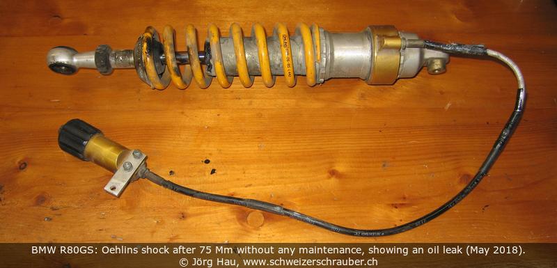
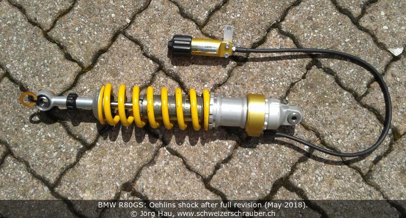

After 75 Mm without maintenance and riding under nasty conditions, the Öhlins shock developed an oil leak in spring 2018 (total mileage of the GS: 199 Mm). I had the shock revised, for a staggering 516 CHF ... but it was worth the money: the dealer found that the preload adjuster was lacking hydraulic fluid, which is the real reason why I always had to crank it up to a setting of at least 7 (of 12), even when riding solo. Now that the shock has been revised, I can finally use the correct setting of "0" when riding solo. Problem solved, after merely 22 years ;-)
Lessons learned: when you get an aftermarket shock, specify your individual weight and your riding style and make sure the manufacturer adjusts it to your specifications. Those shocks are too expensive to have them not properly set up.
After changing the rear shock I felt that the front fork springs needed replacement, too. I changed them (91000 km, 1997-04) against White Power ProLine springs. When I changed the springs I found that the original GS springs are much shorter than the fork and that BMW indeed uses plastic standoffs! In contrast to this, the White Power springs go up to the full length of the fork. The response of the fork improved nicely and at high load it is progressive. I can really recommend them.
Installing new fork springs is actually not very difficult, just a bit tricky. First of all, remove the gas tank - a few screws will always follow gravity, and I prefer if they fall on the engine block instead of scratching my bike's gas tank. In addition, you may want to loosen the handlebar as it is somewhat in the way to remove the caps from the fork. Take care not to "tip over" the bar anyway - you may get air bubbles in the brake system, or brake liquid may leak out. Next, remove the huge screws that hold the turning lights in place - you may use the handle for the spark tool and a small hammer for that.
Now, you need an Allen key of 17 mm (!). Albeit the "short" tubular key from the stock toolset seems to have just the right outer diameter on one end, it is a bit too large - thus, I usually use a home-made insert, consisting of a short (20...30 mm) bolt with 17-mm head and two 17-mm nuts. Remove the caps that close the fork and take care as the two caps are spring-loaded. Remove the springs, put the new ones in (observe direction: narrow winding upwards), and put the whole thing together again.
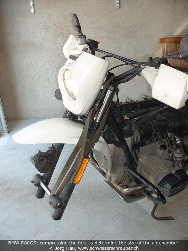 Fork oil level. White Power recommends oil and an air chamber of 160 mm,
measured without the springs and with compressed fork.
Since I do not really want to remove the springs at every change of the fork oil, I followed this
procedure once and determined at the same time the corresponding value for the "normal" fork position.
I found that the above measure of 160 mm corresponds to an oil level of 410 mm below the upper
edge of the assembled and fully relaxed fork (bike on the centerstand, front wheel in the air).
Other riders have reported similar levels, between 408 and
430 mm.
Fork oil level. White Power recommends oil and an air chamber of 160 mm,
measured without the springs and with compressed fork.
Since I do not really want to remove the springs at every change of the fork oil, I followed this
procedure once and determined at the same time the corresponding value for the "normal" fork position.
I found that the above measure of 160 mm corresponds to an oil level of 410 mm below the upper
edge of the assembled and fully relaxed fork (bike on the centerstand, front wheel in the air).
Other riders have reported similar levels, between 408 and
430 mm.
It is important to "pump" the closed (!) fork several times before adjusting the oil level: after draining the fork oil, some cavities are present that are only filled by the movement of the fork. The observed oil level will obviously change during this process!
The resulting oil volume is different from the volume recommened for the original BMW springs, but instead of exactly measuring the oil volume, I simply overfill the fork slightly (400 ml left, 470 ml right), close it and "pump" the fork several times. The excess fluid is then removed by introducing a rigid tube exactly 41 cm into the fork (mark) and aspirating the excess of oil with a plastic syringe. This "aspiration technique" has he additional advantage that it ensures an identical oil level in both legs of the fork.
Fork oil viscosity. The fork oil recommended by BMW, for the fork in its original state, is "Esso Komfort", which is SAE 10W. With the WP springs, I changed from the initial SAE 7.5 (recommended by the manufacturer) to SAE 5-10W from Motorex. - The GS fork uses an interesting system to control compression and rebound damping: Compression damping ("Druckstufe") is entirely controlled by the left fork, while rebound damping ("Zugstufe") is controlled by the right fork. This offers the possibility of some "fine-tuning" using different oil viscosities in the two compartments; recommendations are generally SAE 7.5 (or 7.5W-15) for the left (compression) and SAE 10 (or 10W-20) for the right fork (rebound).
The riding position on the GS is almost perfect for street riding, albeit I'm 190 cm tall. However, whenever I stood on the footpegs, I found that the distance between the footpegs and handlebars was too short for me. I could barely stand upright, my upper body was bent forward and I had trouble to look where I was going.
After (too ;-) many years, I finally installed a pair of 25-mm handlebar risers ("Lenkererhöhung") on the GS. While it does not make a big difference for a sitting rider, the improvement is enormous as soon as I get up and stand on the footpegs. - Such bar risers are available from a number of manufacturers; mine are from SW-Motech. While their finish was far from perfect - the paint came off while they were still in the packaging! -, they fit well and installation took only a few minutes. - The 25-mm version (and reportedly also the 30-mm version) can be installed on the GS without problems, but you may want to make sure that especially the electrical wiring does not undergo any mechanical stress.
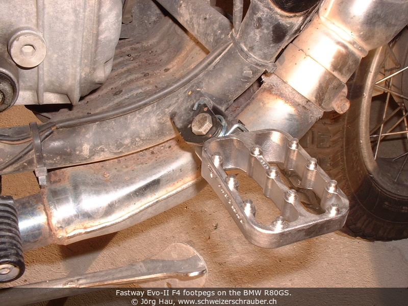
Similar to the handlebar risers, I have been looking for lower footpegs for quite a while, with the aim of both improving the foot-to-handlebar distance and reducing strain on my knees during long rides. There are numerous variants available on the market and finally I settled for a pair of Fastway Evo-II F4 footpegs. They are about 2 cm lower than the stock steel footpegs (the exact number depends on how you measure, since the Evo-II footpegs have rather high "pins" - the number is somewhere between 1.8 and 2.5 cm). In addition, the surface is much bigger (70×25 mm BMW, 84×58 mm Evo-II), which shifts the rear edge 1.1 cm further to the back (!) than the stock footpegs. Due to their overall width, the front edge advances 2.2 cm compared the BMW pegs.
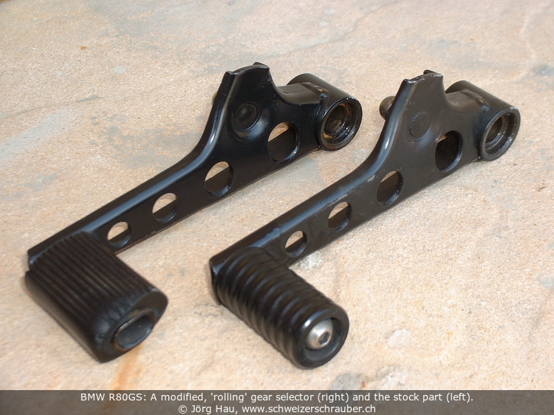
Another item I already installed a while ago is a "rolling" gear selector ("Schaltrolle") - basically a gear lever where the fixed rubber part is replaced by a free-moving roll. The reason behind this modification is that, when you change gears, the rider's foot and the gear lever move in opposite directions. Said "roll" on the lever is supposed to reduce the resulting friction. Such a device can be fabricated from the stock lever; basically you remove the rubber part and replace it with a plastic roll, held in place by a suitable, secured M6 bolt. A drawing is available e.g. at Quargala's webpage (in German, under "Umbau" > "Schaltrolle"). - In my case, I did not notice any significant improvement over the stock item, but this may partially be due to my shoe size of 45. Other riders have reported a noticeable improvement.
I have used the original rubber brake lines for several years without problems. When it was time to replace them due to ageing (4...6 years), I took stainless steel brake lines by Spiegler. The brake is now much more precise to dose and requires - in my very subjective impression - less force. Highly recommended!
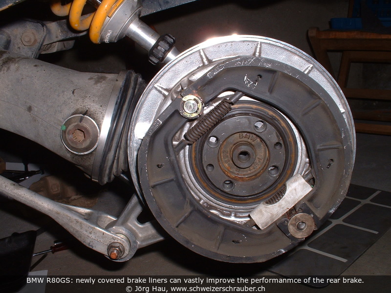 The rear drum brake is generally renowned as "not very effective". After more than 100 Mm
I brought the rear brake pads - still the original, factory-mounted set - to a shop that deals with
clutch and brake repairs. I learned that the liners were basically still fine - nor glassy nor
defective -, but way too hard for this purpose. The shop re-fitted my original brake pads
with new, softer liners ... and since that time my GS has a rear brake that is truly capable of
blocking the rear wheel if I want to. And at a cost that is far below the factory parts.
The rear drum brake is generally renowned as "not very effective". After more than 100 Mm
I brought the rear brake pads - still the original, factory-mounted set - to a shop that deals with
clutch and brake repairs. I learned that the liners were basically still fine - nor glassy nor
defective -, but way too hard for this purpose. The shop re-fitted my original brake pads
with new, softer liners ... and since that time my GS has a rear brake that is truly capable of
blocking the rear wheel if I want to. And at a cost that is far below the factory parts.
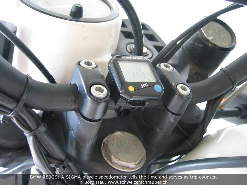
The original bike does not have a clock and the 12V add-on from BMW is large and expensive. I finally got a simple bicycle speedometer that I attached to the center of the handlebar. Those thingies have the advantage that they are vibration resistant and waterproof, have their own battery (no additional wiring required), can be calibrated accurately (the Metzeler Enduro 4 has 2200 mm circumference, the Mitas E-08 2155 mm) ... and when I connected the speedometer my GS was finally equipped with four different tripmeters! I use the second "original" counter to control my range (km since topping the last time), the tripmeter on the bicycle counter gives today's total km, and the "main counter" on the bicycle counter gives me the distance since the last oil change. Since I installed it, I don't want to miss it.
If you get such a bicycle speedometer, make sure that it can support the speed of your bike. Most of the better brands indicate the top speed in the brochure that comes along with the part. Mine is a simple Sigma Sport BC500. The only modification required was the replacement of the original cable by a longer one (I used a thin coaxial cable).

One annoying feature of the GS is the stock taillight. Over time, the tail lamp develops a tendency to switch itself off.
The problem is not related to the filament burning out — this bike has barely eaten 2 or 3 lamps in 200+ Mm. Instead, the contacts oxidize: after a while of riding, some oxide deposit is present both on the contacts of the bulb and on their metal-feather counterpart on the taillight. This deposit causes intermittent failures of the tail light. A clear symptom is that the tail light can be toggled on and off by tapping it with your hand ;-)
I have tried different solutions such as scrubbing, bending, using Kontakt spray and covering the contacts with a fresh layer of solder tin, but none of these helped permanently. In summer 2016 I decided it was time for a different approach ... and built my own LED tail light.
The design is straightforward: two series of LEDs replace the two lamp filaments. The number of red LEDs corresponds roughly to the “Wattage” of the standard taillight, with a 21+5 W lamp compared to 19+5 LED. The red LED are specially designed for brake lights in cars, they are specified with 9000 mCd @ 70 mA and a whopping 85° viewing angle. Warm-white LED are used for the license plate light; these are standard 5-mm LED, bent downwards and specified with 23000 mCd @ 20 mA.
I offer these units for sale, and there are also distinct versions for the BMW /7 and the /5 and /6 series taillights. If you are interested, follow this link.
Albeit the light is marvelously bright, I was a bit worried that light distribution might not be not as homogeneous as the original bulb's light, so I ran a short series of experiments in the twilight of my garage:
The following two series of images differ only in the exposition time: the first series was taken with 1/10 s and the second series with 1/6th s (click to see full size). They show:


Conclusion: The new design is much brighter than the original bulb, and light distribution is also much more homogeneous! I might even need to reduce the brightness of the normal taillight since it might be too bright at night - to be verified.
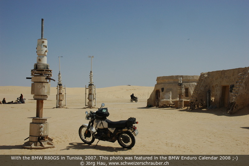
A really useful accessory is the larger bash plate. This is a genuine BMW part that was originally designed for the "Paris-Dakar" kits. It is much larger and thicker than the original part (for a direct comparison, see the picture) and protects the complete underside of the engine, including downpipes, intermediate muffler and centerstand. In addition, the smooth surface (no holes) allows the bike to "slide" over rocks if the plate hits them. I found it particularly useful in regions with harsh or rocky roads; after the 2008 spring trip to Tunisia, particularly the rear plate had a number of deep scratches that would certainly have damaged the centerstand and exhaust collector box.
") The improved protection has a small downside: Due to the higher weight, you may want to use stronger springs for the
centerstand (or simply install additional, "crossed" springs).
Another point is that the bash plate installation complicates oil change: Any oil spilled during oil filter removal
will be spread by the front bash plate ... and oil coming from the drain plug will hit exactly the top of the centerstand's
skid plate, thus being guided in two different places :-(
Thus, I prefer draining the oil with the bike on the sidestand and for changing the oil filter I remove the bash plate completely.
The improved protection has a small downside: Due to the higher weight, you may want to use stronger springs for the
centerstand (or simply install additional, "crossed" springs).
Another point is that the bash plate installation complicates oil change: Any oil spilled during oil filter removal
will be spread by the front bash plate ... and oil coming from the drain plug will hit exactly the top of the centerstand's
skid plate, thus being guided in two different places :-(
Thus, I prefer draining the oil with the bike on the sidestand and for changing the oil filter I remove the bash plate completely.
Originally, the GS was equipped with Metzeler Enduro 3, which is a tire that has been developed specifically for the BMW GS series. Indeed it is "the" perfect tire for this bike, with wonderful grip on dry and wet roads as well as off-road, but wear is considerable: The Enduro 3 lasts about 6...9 Mm on the rear wheel, about 12 Mm on the front wheel. Usual tire pressure: 2.2/2.5 bar (front/rear) solo, up to 2.4/2.9 bar fully loaded on street.
In search for a longer-lasting alternative I have tried the Michelin T65 for a while - a few thousand km - on the rear wheel. On dry roads it is a good tire, but as soon as it gets wet it is so slippery that I can only classify this tire as "dangerous". Fortunately it is no longer available.
Between 1992 and 1995 I rode my GS with street tires. The big advantage was that the bike rolled notably more smooth, and I got the impression that handling was also a bit better. The Metzeler ME33 was one of the few street tires that were available in 21" sizes. A good tire with good grip, but as soon as it was a bit "used" the tire became somewhat slippery in the corners - I had to change the tire after about 12 Mm. On the rear wheel, the Metzeler ME55 was a perfect street tire for this bike. No problems on any kind of road, excellent grip, lifetime 7.5...9.5 Mm.
The Metzeler Enduro 4 Radial was a radi(c)ally different tire - much more road-oriented, with large amounts of positive profile. Lifetime was about twice that of the Enduro 3, with reasonable handling on dry terrain. In the Radial version (only available for the rear wheel), the properties were identical to that of the Enduro 4, but lifetime was considerably higher: I got between 11 and 14 Mm from a rear tire. Usual tire pressures were identical to the Enduro 3 above; for long trips on gravel roads, I reduced tire pressure down to 1.8/2.0 bar or less - the bike was much better to handle on loose ground. - For the front wheel, Metzeler has changed the profile of the Enduro 4 a few times. The earlier versions developed a "sawtooth" profile that made tire changes necessary after 8...10 Mm. The more recent versions easily lasted for more than 10 Mm.
 In late 2003, I changed for quite a while to Mitas E-08 for the "usual" riding. They have a
much "rounder" profile than the Metzeler, which leads to a surprising improvement in handling.
This tire is among the best I ever experienced on this motorcycle; both on dry and wet roads they are excellent.
In particular the front tire has surprising properties: Even when it has already developed a sawtooth profile, it still sticks very
well to the road and braking behaviour has clearly improved.
In addition, its rather "open" profile allows for very relaxed riding even in deep gravel, where a Metzeler Enduro 4 would simply fail to guide the front wheel.
Tire pressures are as mentioned above; with reduced pressure (1.8 and 2.0 bar, respectively) even long passages on harsh gravel are possible without problems.
- The rear tire lasts about 7 Mm, the one on the front wheel about 10 Mm. The only downside is that, for some reason that escapes me,
the tubeless versions are more and more difficult to obtain. In addition, the price for the E-08 has almost doubled in five years, so I switched to the Heidenau K60 (see below).
In late 2003, I changed for quite a while to Mitas E-08 for the "usual" riding. They have a
much "rounder" profile than the Metzeler, which leads to a surprising improvement in handling.
This tire is among the best I ever experienced on this motorcycle; both on dry and wet roads they are excellent.
In particular the front tire has surprising properties: Even when it has already developed a sawtooth profile, it still sticks very
well to the road and braking behaviour has clearly improved.
In addition, its rather "open" profile allows for very relaxed riding even in deep gravel, where a Metzeler Enduro 4 would simply fail to guide the front wheel.
Tire pressures are as mentioned above; with reduced pressure (1.8 and 2.0 bar, respectively) even long passages on harsh gravel are possible without problems.
- The rear tire lasts about 7 Mm, the one on the front wheel about 10 Mm. The only downside is that, for some reason that escapes me,
the tubeless versions are more and more difficult to obtain. In addition, the price for the E-08 has almost doubled in five years, so I switched to the Heidenau K60 (see below).
 Another tire from the same manufacturer is the Mitas E-07, which I used on the rear wheel (in combination
with E-08 front). The relatively open profile yields good traction on loose
ground; overall handling and properties on tarmac are comparable to that of the E-08.
A disadvantage is that the tire is very noisy; its profile induces quite some "singing".
Another tire from the same manufacturer is the Mitas E-07, which I used on the rear wheel (in combination
with E-08 front). The relatively open profile yields good traction on loose
ground; overall handling and properties on tarmac are comparable to that of the E-08.
A disadvantage is that the tire is very noisy; its profile induces quite some "singing".
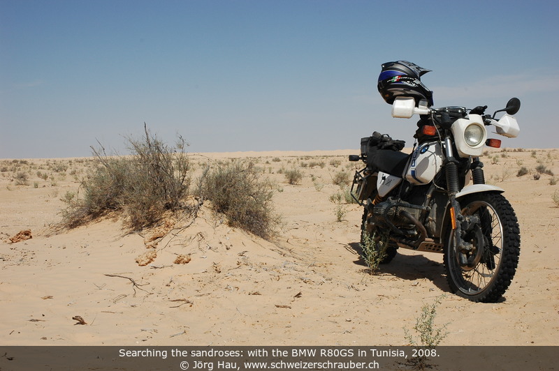
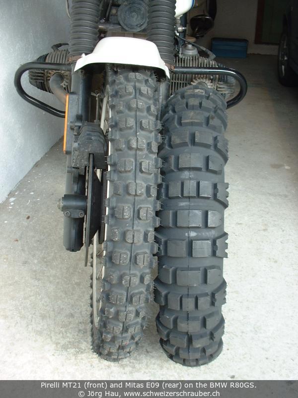 For "real" offroad and sand riding (Tunisia, spring 2007 and 2008) I equipped the GS with
Pirelli MT21 at the front and Mitas E09 at the rear. With my limited experience, I would classify the Pirelli as a
good front wheel tire for desert riding; it offers quite some stability, but it also has a pronounced tendency to "climb" out of
sand tracks if your speed is not high enough. The Mitas E09 "just worked"; I could not find any particularly weak point, albeit
I guess that traction and direction stability in sand could be better. It lasts for more than 8 Mm. -
For "real" offroad and sand riding (Tunisia, spring 2007 and 2008) I equipped the GS with
Pirelli MT21 at the front and Mitas E09 at the rear. With my limited experience, I would classify the Pirelli as a
good front wheel tire for desert riding; it offers quite some stability, but it also has a pronounced tendency to "climb" out of
sand tracks if your speed is not high enough. The Mitas E09 "just worked"; I could not find any particularly weak point, albeit
I guess that traction and direction stability in sand could be better. It lasts for more than 8 Mm. -
 Both tires show excellent properties on tarmac and allow cornering similar to street tires and as long as the steering head bearing
is adjusted correctly the bike remains steady even at high speed. Of course they are rather noisy, due to their open profile.
The tire pressure I used on tarmac was usually about 1.6...2.0 bar front, 1.8...2.3 bar rear;
in the sand, I used 0.8...1.2 bar on both wheels without problems (and without tire holders).
During the second Tunisia trip in spring 2008 (where we rode lots of gravel and sand roads),
I used 1.1 bar everywhere, including long sections on tarmac.
- The MT21 has an unusual wear pattern; it is the flank of the tire that wears out first, resulting in a somewhat
"triangular" tire profile. As a result, I had to change my first MT21 after about 5500 km and the second after
6800 km, which represents the shortest lifetime I ever observed for a front tire.
Both tires show excellent properties on tarmac and allow cornering similar to street tires and as long as the steering head bearing
is adjusted correctly the bike remains steady even at high speed. Of course they are rather noisy, due to their open profile.
The tire pressure I used on tarmac was usually about 1.6...2.0 bar front, 1.8...2.3 bar rear;
in the sand, I used 0.8...1.2 bar on both wheels without problems (and without tire holders).
During the second Tunisia trip in spring 2008 (where we rode lots of gravel and sand roads),
I used 1.1 bar everywhere, including long sections on tarmac.
- The MT21 has an unusual wear pattern; it is the flank of the tire that wears out first, resulting in a somewhat
"triangular" tire profile. As a result, I had to change my first MT21 after about 5500 km and the second after
6800 km, which represents the shortest lifetime I ever observed for a front tire.
 Since summer 2008, I am running the Heidenau K60, initially only on the front wheel and combined with Mitas E-07, E-09 and Heidenau K60 on the rear.
In spite of the open profile, the tire behaves neutral and does not exhibit any particular problems or weaknesses; I definitively consider
it as a true alternative to the Mitas E-08, with much more offroad capability. As of summer 2014, I have used this tire on rough mountain trails
in the Frech/Italian Alps as well as for rapid riding on tarmac, dry or wet - this is clearly a tire that fits my needs and my riding style perfectly.
Lifetime seems to be varying; the first K60 on the rear wheel lasted for 8.2 Mm, the second only 5 Mm. The front tire lasts around 12.5 Mm.
- In 2012, Heidenau added the K60 Scout, primarily to meet the requirements of heavy "adventure" bikes, yet both tires are still available.
Lifetime seems to be a bit longer (8-10 Mm on the rear wheel).
Since summer 2008, I am running the Heidenau K60, initially only on the front wheel and combined with Mitas E-07, E-09 and Heidenau K60 on the rear.
In spite of the open profile, the tire behaves neutral and does not exhibit any particular problems or weaknesses; I definitively consider
it as a true alternative to the Mitas E-08, with much more offroad capability. As of summer 2014, I have used this tire on rough mountain trails
in the Frech/Italian Alps as well as for rapid riding on tarmac, dry or wet - this is clearly a tire that fits my needs and my riding style perfectly.
Lifetime seems to be varying; the first K60 on the rear wheel lasted for 8.2 Mm, the second only 5 Mm. The front tire lasts around 12.5 Mm.
- In 2012, Heidenau added the K60 Scout, primarily to meet the requirements of heavy "adventure" bikes, yet both tires are still available.
Lifetime seems to be a bit longer (8-10 Mm on the rear wheel).
While I am active in the HPN Forum for more than 15 years, it was only during the HPN Forumstreff 2015 that I decided to order a HPN frame reinforcement.
Before this date, I was somewhat confused by the fact that most HPN bikes that I knew involved costs of at least 7 k€. I was unaware of the fact that besides these in-depth HPN Sport modifications, HPN also offers their basic frame reinforcement for a very reasonable price: as of 2017-07, the list price is less than 800 €.
I placed order in late 2015, quickly received the confirmation together with my frame number (0619) and ... waited.
In summer 2017, HPN was ready to receive my frame. Within 24 hours, I completely disassembled the bike and sent the frame to Germany. In the meantime, I changed the timing chain, changed all oils, replaced the pushrod seals, powder-coated the rear subframe, centerstand and luggage carrier, washed all cables and took care of the plastic parts.
Only five weeks later, the reinforced frame was on its way back. I received it on 2017-08-03, reassembled the bike over a period of 2 weeks and on 2017-08-20, HPN 619 hit the road for the first time!
Maintenance is as much art as it is science.
After about 47'000 km, oil consumption was excessive: more that 1 l per 1000 km. Some friends riding with me complained that the GS started to smoke like a two-stroke engine, especially when I had used the motor brake for a while (downhill). Upon removal of the sparks I could see that the combustion chamber of the right cylinder and the shaft of the exhaust valve were wetted with oil, so there was really something wrong. I finally decided to have the cylinder heads rebuilt.
I contacted BMW in Munich before the "operation" to ask for a refund. The first reason was that I don't consider it as normal that an 800-cm3-engine has to be rebuilt after less than 100'000 km. The second reason was that I had contacted BMW before buying the bike and asked about the "expected lifetime" of the motor (at that time, there was a long-distance test in the "Tourenfahrer" magazine which clearly stated that the engine of the 100GS needed a rebuild after 40'000 km). BMW replied 1990 that a usual lifetime of more than 80'000 km could be expected before the engine would need revision.
Well, upon my request they regretted the problems with my GS and said that it was certainly not normal that the valve guides were worn out after 47000 km, but I should please get in contact with my local BMW agency.
That is what I did and the rebuild was finally done in 1993, at about 58000 km. At WüDo in Dortmund (I was living close by at that time) this cost me about 1000 DM, with two third of that for the material and the rest for the work.
 The picture shows an inlet valve (left) and an outlet valve. The colours were
somewhat falsified on the scanner ... but that shows nicely the "wear and tear"
on the valves.
The picture shows an inlet valve (left) and an outlet valve. The colours were
somewhat falsified on the scanner ... but that shows nicely the "wear and tear"
on the valves.
It was found that all four valves had considerable play in their guide perpendicular to the primary axis (that is, they "wiggle" if you move them laterally). In addition, the outlet valves were completely worn out. The cylinders and pistons were nice and rather clean (except for some coal deposits, origining from the oil that had been carried in through the worn-out valves and that had burned). During the next years and up to about 120 Mm, the motor was always fine and never showed an oil consumption exceeding 0.5 l/1000 km.
With all these data, I re-contacted BMW in Munich to ask for a refund. They regretted again the problems with my GS, but "please understand that a technical defect may occur even with a BMW motorcycle and that we cannot always explain this. After more than three years we cannot participate in the costs."
The second head overhaul was performed in 2007-04, at 146400 km. It is documented on a separate page. Material costs were about 300 EUR.
Over the years, my GS started to develop a certain amount of "mechanical noise". When you are riding the same bike all the time, you don't notice these changes as they introduce themselves very smoothly. However, if someone else listens to the noise he will be probably be able to tell you that it has changed since the last time.
That was what happened at my local BMW dealer. He found my GS rather noisy and said that it would be a good idea to change the timing chain in a not-too-distant future. Indeed the bike was rattling pretty much, which was best heard in his workshop where the noise echoed off the walls. My bike had 110'500 km on the counter and still the first timing chain. There were not apparent signs of misbehaviour, but the idea of changing the timing chain sounded reasonable to me.
Well, I asked how much he would charge for this and he answered "something like 500 CHF".
Oops.
That was the moment I decided to do it myself.
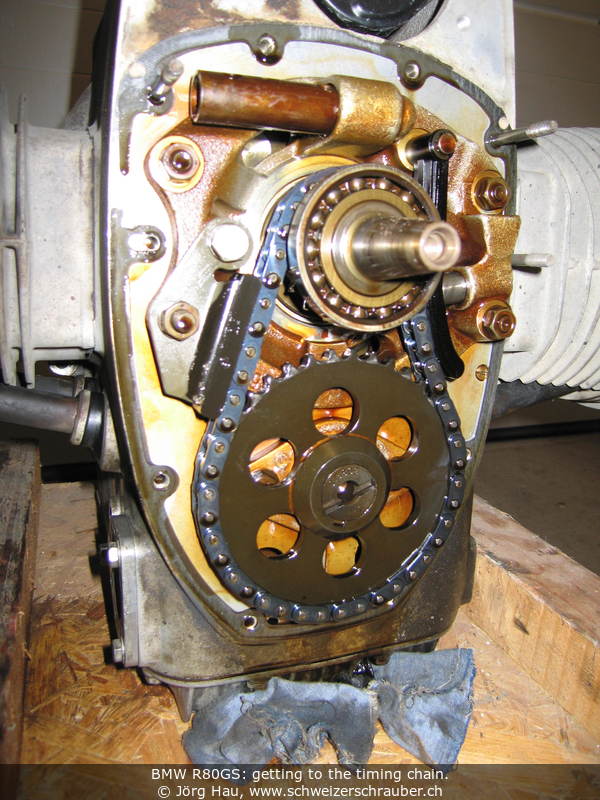
I understood later on that most of this sum of money was not for the parts; they're actually pretty cheap. Even the action of changing the timing chain "as such" is actually not difficult. The challenge is to get to it, as there is an amazing amount of stuff to be removed before you can access the chain - covers, electrics, alternator, even the exhaust downpipes and crashbar bolts have to be removed. I had never dismantled the bike as far as this and it was a real good learning experience. Here we go.
This is the list of parts that are needed, with part number updated and prices given in CHF as per June 2017 (2nd timing chain replacement). Compared to 2001 (1st timing chain replacement), prices for most parts remained rather constant (the timing chain went from 30.50 CHF to 28.05 CHF, the seal -337 654 (former -255 011) from 12.20 CHF to 8.20 CHF. For other parts, prices increased significantly: the chain tensioner went from 3.30 CHF to 8.75 CHF, its spring from 0.40 CHF to 6.10 CHF (15-fold), and the slide rail tripled from 10.40 CHF to 30.25 CHF.
--------+-----------------+------------------------------------------------
   CHF      Part number     Designation (EN/DE/FR)
--------+-----------------+------------------------------------------------
  28.05   11 31 1 335 580   Timing Chain/Steuerkette/Chaîne de distribution
   8.75   11 31 1 338 185   Chain Tensioner/Kettenspanner/Patin
   6.10   11 31 1 335 584   Spring/Feder/Ressort
  30.25   11 31 1 335 576   Slide Rail/Gleitschiene/Patin
   4.88   11 14 1 338 428   Gasket/Dichtung/Joint
   8.20   11 14 1 337 654   Seal/Simmerring/Simmerring
--------+-----------------+-------------------------------------------------
In addition, get some bright paint (correction fluid like "Tipp-Ex" is just fine), a few Nylon cable binders and high-temperature anti-seize for the exhaust nuts, e.g. copper paste, ceramic paste, or "Optimol TA". (Some people advise against the use of copper paste in connection with aluminium parts.)
Among the "unusual" tools, there is the wrench for the exhaust nuts. Hammer with plastic head. Some tool to remove the alternator (see below). Small pair of pliers. Hair dryer, or hot air gun. Strobe lamp to adjust ignition timing after reassembly.
I assume that you are in good mood, self-confident and that you have some practical experience in mechanics on this bike. If you do this for the first time, plan at least six hours - now that I have figured out a few tricks, I might be able to do it in about half of that time.
The engine must be cold and clean. This time you are really allowed to use a high-pressure cleaner, but only for the engine block.
Before starting anything else, make sure you are able to remove the exhaust downpipes (german: "Auspuffkrümmer"). You have to take them off, as the interference tube will interfere (!) with the lower part of the timing chain cover. If your downpipes haven't been removed for a while, put some thin oil ("Kriechöl") on the threads and wait a few hours, then set on the tool and rotate the nuts with a hammer. If you screw up the exhaust threads on the engine, you're in expensive trouble, so be careful.
Now we can "really" start.
Time to breathe. You're exactly halfway through it. Have a break. Wash your fingers. Go check your e-mail. Relax.


Note: the old photos from the 2001 timing chain maintenance have been replaced with better pictures from the 2017 maintenance.
I took this time to examine the old versus the new parts. On my GS, I found that there was no "really considerable" wear on most parts. I could have reused the slide rail immediately and even the chain tensioner was in a pretty good shape. Its spring, however, had lost some 10 percent in length. When I suspended the old and the new timing chain next to each other, I found the old one not to be elongated. However, it was possible to lift the old chain a bit off the cogwheels and this was not the case with the new one. So there was a good reason to replace it.
By the way, if this is the third or fourth chain, you may need to replace the cogwheels on the crankshaft and on the camshaft. I've never done this, so I'll omit it here.
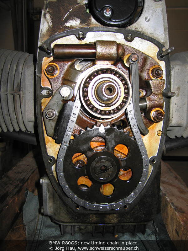
Time to install the new chain.
That's most of it. Now reassemble the parts that are left:
Have fun!
If you own a different BMW, an article from Jim Buchanan and/or from Matt Parkhouse may be helpful.
At about 116000 km, I recognised a "howling" noise coming from the gearbox of my GS. I could still ride the bike without any problems, but this noise was not normal ... so I decided to have the gearbox revised.
The bad news is that overhauling the gearbox is a job that can not be done with the tools of a do-it-yourself mechanic. To open the gearbox, you need at least the flange puller(s) from BMW and a a pneumatic wrench plus a few other tools would also be helpful.
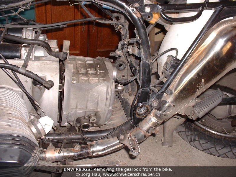
The good news is that you can save a sound amount of money by removing and re-fitting the gearbox yourself. Removal of the gearbox is actually not very difficult, but it is a very time-consuming job: My local BMW dealer assumes some 5 hours to do the job, so this easily saved me 450 CHF even if I did "only" the removal and re-installation myself.
The only special tool needed is a 27-mm tubular key (or the 27-mm nut from a ratchet set), a torque wrench with hex inserts (to adjust the rear swingarm bearings) and a 15-mm wrench for the paralever rod. All the rest can be done with the stock toolset, although e.g. a ratchet set will speed up work considerably. - In addition, get some anti-seize (e.g. copper paste or MoS2 grease) and BMWs driveshaft grease (Staburags or MP3). - There are lots of parts to remove, so I was prepared to find myself with many screws, nuts and bolts. I used to re-attach all those nuts and bolts to their original place immediately and I used my digital camera to take lots of pictures.
So, here we go ...:
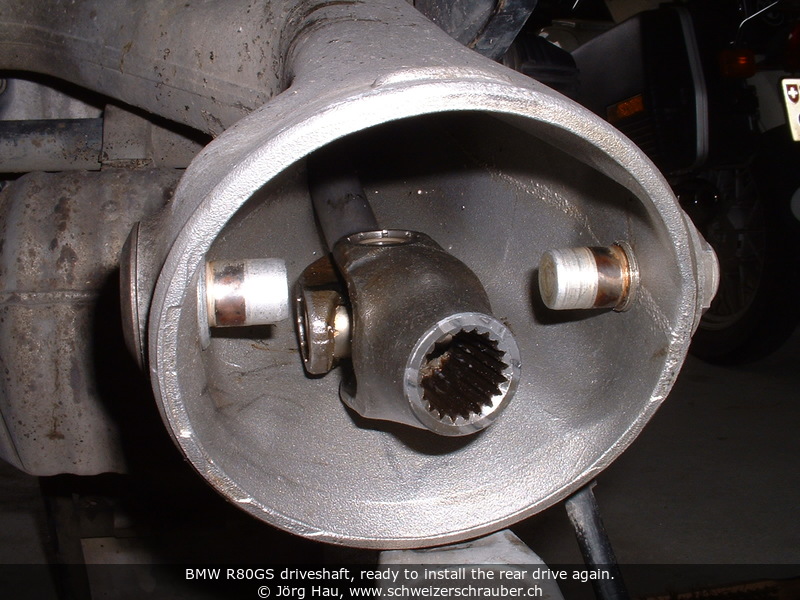
Have a break. If your gearbox needs repair and you have to wait for it, this may be a good moment to clean the carburetors, or to inspect the starter motor (now that is perfectly well accessible). In addition, check the driveshaft rubber bellows for holes - now is the perfect moment to change them. To inspect the shaft drive, just pull it away from the rear drive. The joints should have some black grease oozing out. Grip both ends of the shaft drive firmly with both hands, twist and turn it in all directions - if you feel any play, the driveshaft needs repair.


The gearbox overhaul is described in another section on this site.
Diagnostics: We found that the howling noise was caused by a defective bearing. This was the bearing that is sitting on the clutch side of the outlet cam. This bearing is the "classical" point of failure for BMW gearboxes: It takes not only the radial forces from the other cams and the gear cogwheels, but also the thousands of little axial shocks from the shaft drive ... in other words, this bearing is supposed to absorb forces that it is not designed for. On my GS, it was still far from catastrophic failure, but the bearing had developed some 3 mm of axial play.
Before reinstalling the gearbox, make sure you can shift through all the gears and back. It seems that it is possible to assemble the gearbox "wrong", so that you can shift gears up - but then you are stuck ...
A second point to verify: At the exit flange of the gearbox, the seal (Simmerring) must be installed with the flat end outside. At the upper end of the seal, there is a small triangular cut-out in the housing, which formerly served as a vent ... this must be sealed, otherwise oil will leak from the gearbox into the rear drive. Don't ask me how I learned this ;-)
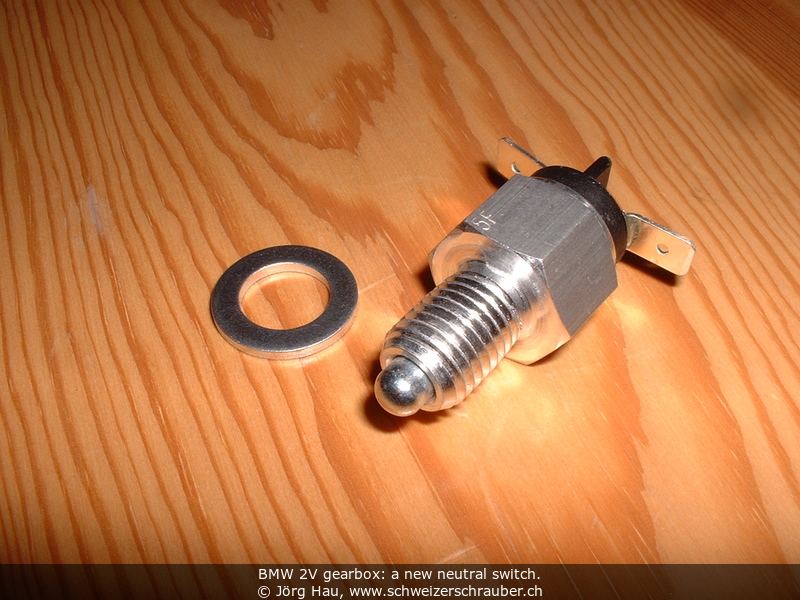
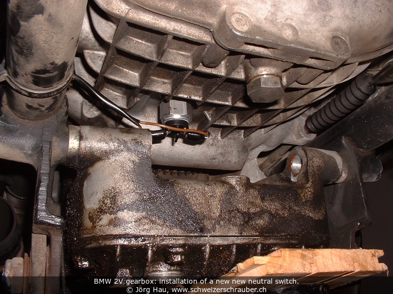
At about 143000 km, I noticed oil dripping from the gearbox. Not a real "issue", but since I do not like oil stains on the garage floor it was time to change the switch.
Changing the neutral switch as such is not difficult ... the problem is getting to it, since it is located under the gearbox, right above a recess in the oil pan of the engine. To get there, you have basically two possibilities: either you remove the gearbox from the bike, or you remove the exhaust collector box and change the switch with the gearbox in place.
In the past I had removed the gearbox a number of times, so I decided to try the second path here. The part you need is the switch 61 31 1 243 097 plus its washer; total cost was about 48 CHF in late 2006. Special tools: A car lift, a hammer, eventually a torque wrench. If your exhaust system has not been disassembled for a while, add some thin oil ("Kriechöl"), a hot air gun, or whatever you prefer to get these bolts moving ;-)

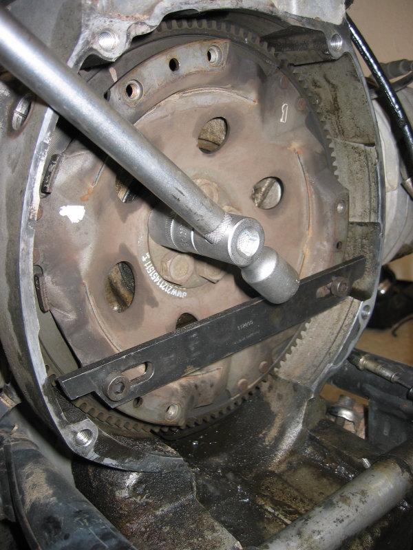
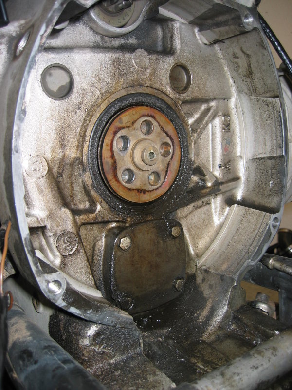
Early in 2009 I noticed some oil drops on the garage floor under the engine. Upon closer inspection, it turned out that there was also some oil mist on the connection between the engine and the gearbox. The diagmosis was clear: the rear crankcase main seal was toast.
With more than 158 Mm on the engine, this was not too much of a surprise.
Changing the seal is not that difficult, but it is time-consuming since you need to strip the bike down to the bare engine. I spent about an afternoon for disassembly, changing the main seal and re-fitting the clutch and it was the first time that I did this job.
Tools: You will need all the tools mentioned under gearbox removal above, something to block the clutch in the engine housing (BMW tool number 11 2 800), and a tool to insert the new seal into the crankcase housing (BMW tool number 11 1 880). I could borrow both from my local BMW dealership :-) - In addition, get some degreaser.
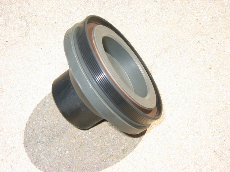
Spare Parts: While you're at it, you may want to change not only the crankcase seal and the associated O-ring, but also the O-Ring of the oil pump and the simmerring at the entrance of the gearbox. Part numbers:
--------+-----------------+------------------------------------------------
   CHF      Part number     Designation (EN)
--------+-----------------+------------------------------------------------
  xxxxx   11 11 1 338 342   Crankcase/shaft seal ("Simmerring", 100X80X10)
  xxxxx   11 22 1 337 099   O-Ring/gasket crankcase
  xxxxx   11 41 1 335 895   O-Ring/gasket oil pump
  xxxxx   23 12 1 338 726   Gearbox entrance seal ("Simmerring")
--------+-----------------+-------------------------------------------------
That's it - you're exactly halfway through it. Clean all surfaces thorougly. Have a break.


Assembly is performed almost exactly in the reverse order of disassembly:
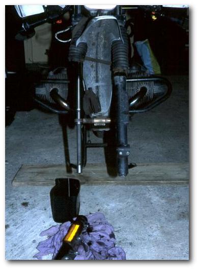
The BMW R80GS has a 40 mm Marzocchi fork. At 110000 km, mine had an oil leak on the right fork. From the first appearance of oil mist to a leaking seal (with oil dripping out) it took less than 200 km! However, with sufficient care we could still go for 400 km with full load across four passes in the Alps. If this happens to you, make sure that you prevent the fork oil from dripping into the brake system or onto the tire! A pretty well-working solution is to take a piece of tissue (old towel or so) of about 30 x 30 cm and to wrap that around the fork, under the dust "bellows". It will absorb oil during the ride, but afterwards please park the bike somewhere where you can collect the oil that will "bleed" from this tissue.
I decided to change the seal on my own. Here's how. - Plan enough time; you may be able to do this in two hours, but you may easily need more!
 Have a break. Most of the work is done!
Have fun!
If the clutch lever starts to feels "sticky" (as if the clutch cable would break soon), you are probably encountering a problem that seems to haunt virtually all 2V GS models: The piston of the clutch mechanism ("Kupplungsdruckkolben") has swollen and is stuck in its guide of the gearbox housing. As a consequence, with a hot engine (commonly after a run on the highway) the clutch separates, but does not re-engage again ... and slips.
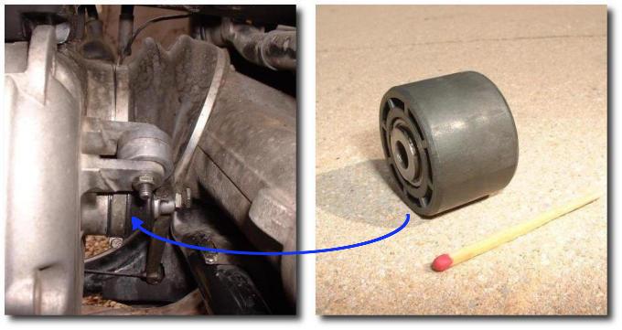 Luckily, the fix is rather easy: Just take off the clutch lever at the rear
end of the gearbox and withdraw the rubber cap. Under this cap you will find a spring and a
cylindric device that can be withdrawn with a pair of tweezers
(yes, it's a bit of fiddling). This device is the infamous piston.
The outer diameter of this piston must be at least 28.60 mm and at maximum 28.75 mm. You can
either buy a new part (about 35 EUR), or simply have it machined down to 28.60 mm (which
is what I did). Re-install everything and your clutch will be fine again.
Luckily, the fix is rather easy: Just take off the clutch lever at the rear
end of the gearbox and withdraw the rubber cap. Under this cap you will find a spring and a
cylindric device that can be withdrawn with a pair of tweezers
(yes, it's a bit of fiddling). This device is the infamous piston.
The outer diameter of this piston must be at least 28.60 mm and at maximum 28.75 mm. You can
either buy a new part (about 35 EUR), or simply have it machined down to 28.60 mm (which
is what I did). Re-install everything and your clutch will be fine again.
On my GS, this happened after more than 120 Mm during a sunday afternoon ride. I don't know why this piston starts to swell after 14 years, but at least the fix was easy.
Thanks to Markus Kraus for his detailed information!
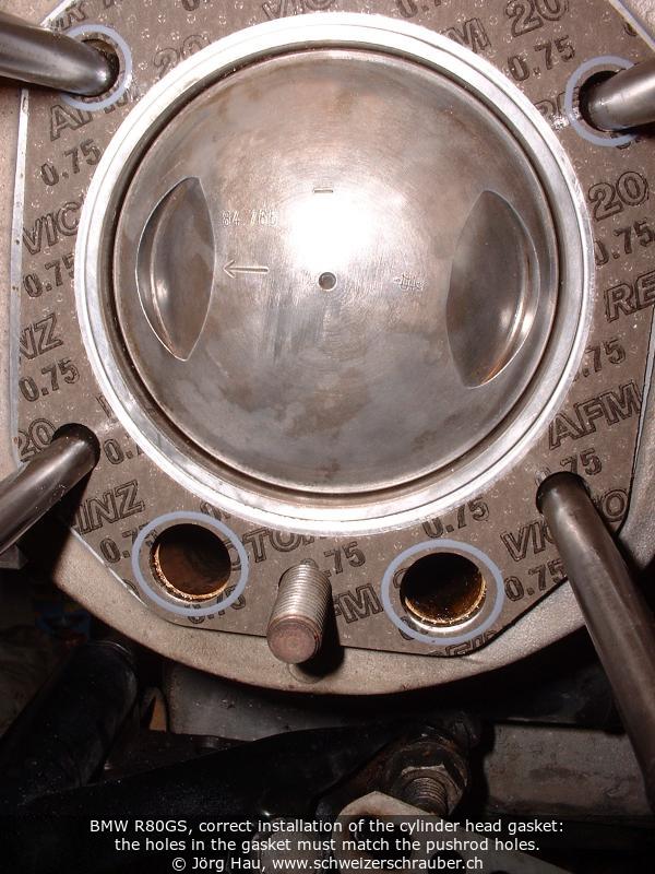
After several years, my GS showed signs of oil leakage at the pushrod base seals. This is probably not a "real" problem as long as there is just some slight oil mist, but it becomes annoying once the oil starts to drip out.
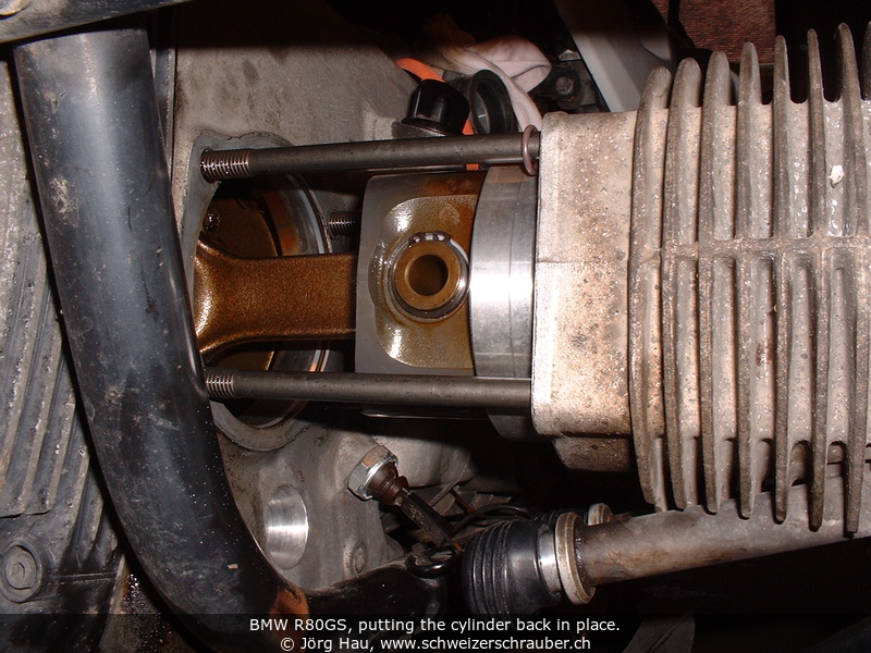
Repairing the leak "as such" is easy, as you just need to change the four pushrod seals. The bad news is that to change the pushrod seals, you need to take the cylinders off ... which means that you can spend a full afternoon with this work. However, the good news is that if you have already some practical experience in mechanics on this bike, and you are in good mood and self-confident, you can do it yourself.
Most of the work can be done with the stock toolset. As for the special tools, you need the wrench for the exhaust nuts, a hammer with plastic head, a pair of pliers for circlips ("Seegerring-Zange"), and a good torque wrench with hex inserts. A ratchet set can speed up work.
The list of parts that you are probably going to replace:
--------+-----------------+------------------------------------------------
 amount     Part number      Designation
--------+-----------------+------------------------------------------------
   4      11 32 1 262 995   Pushrod Seal/Gummistopfen/Bouchon de caoutchouc
   2      11 11 1 337 567   O-Ring/Joint torique (Cylinder base)
   4      11 11 1 262 141   Gasket Ring/Dichtring/Anneau d'étanchéité
   2      11 12 1 338 716   Cyl. head gasket/Zyl.kopfdicht./Joint de culasse
   2      11 12 1 338 426   Gasket/Deckeldichtung/Joint de couvercle
--------+-----------------+-------------------------------------------------
In addition, get some liquid sealant. I have used both Loctite 5926 and Würth "Silikon Spezial 250" with success, but Hylomar blue or similar material reportedly does the job (the important point is that it must resist hot oil up to 150°C at least and no acetic acid should be set free during curing). Also, get some high-temperature anti-seize for the exhaust nuts, e.g. copper paste, ceramic paste, or "Optimol TA" (Note: some people advise against the use of copper paste in connection with aluminium parts). Some degreaser or similar solvent.
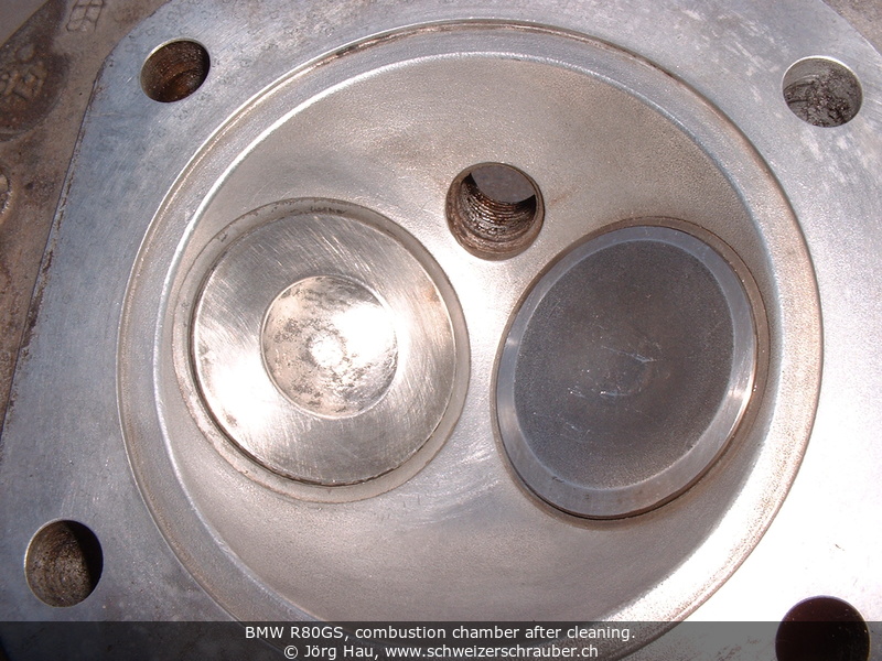
If you do this for the first time, plan at least 1.5 h for the removal and about 2.5 h for the re-installation, plus ample time in between to clean the combustion chambers. I recommend to make lots of notes and pictures. Make sure you do not mix up parts: neither left and right, nor intake and exhaust ... better prepare at least two different, labelled (!) boxes for the parts.
The engine must be clean. You may want to use a high-pressure cleaner to remove oil residues and other crud, in particular abrasive stuff like sand, from the engine. You do not need to drain the engine oil.
Before starting anything else, make sure you are able to remove the exhaust downpipes (german: "Auspuffkrümmer"). If your downpipes haven't been removed for a while, put some thin oil ("Kriechöl") on the threads and wait a few hours, then set on the wrench and rotate the nuts with a hammer. If you screw up the exhaust threads on the engine, you're in expensive trouble, so be careful.
That's it ... take a break.
This may be a good time to test the heads for leaks: If you pour some solvent (alcohol) in the inlet or exhaust chamber, nothing should leak into the combustion chamber ... otherwise it's time to have the heads overhauled.
Remove all the old seals and clean the sealing surfaces from crud, sealer residue etc. You may want to take the time to clean combustion chambers and pistons ... I have used oven cleaner to remove most of the oil coal and various mechanical tools to remove the solid residues. Make sure not to scratch anything, as a scratch will act as a "crystallisation point" for the build-up of new deposits. Thus, the last step should be polishing and washing with clean, dust-free solvent.


Commonly, wear and tear of the final drive go unnoticed for a long time, as the noise builds up very gradually. I noticed this problem only when someone else spun my GS's rear wheel and commented on the rushing noise with "ah yes, this bearing is dead, too". Indeed the rear wheel started to have some axial play (funny enough, only in one position). A while later I noticed that the rear drive was getting very hot even after only 30 km of riding, so it was time to change.
Repairing the final drive requires exchange of the main bearing plus some delicate adjustments; common wisdom (and even BMW dealers) says that it may be cheaper to get a second-hand final drive. This is indeed what I did and in spring 2005 I changed the rear drive. The "old" one is now awaiting repair, but in the meantime I can ride the GS with the "new" rear drive ;-)
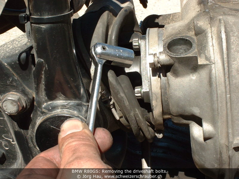
Swapping the final drive is technically not difficult, but it requires quite some tools and fine adjustments. This work is safety-related, so you should know what you are doing. Note especially the positions (depths, angles) of the major nuts, bolts and clamps before unmounting them.
You will need some tools that are not part of the stock toolset: A 27-mm ring key, a 15-mm wrench for the paralever rod, a 12-mm hex ("Inbus") key with a long extension, one torque wrench covering at least 40 to 105 Nm and another one for the range 5 to 10 Nm (to adjust the rear bearings).
In addition, get some anti-seize (e.g. copper paste or MoS2 grease), BMWs driveshaft grease (Staburags or MP3) and a thread sealant. For the latter, the BMW workshop manual lists Loctite 242 (medium stregth, can be removed with tools), their spare parts catalogue mentions 2701 (extra strong, cannot be removed without heat). I used Loctite 243, which seems to be an improved successor of the 242.
It will very probably be required to replace the two paralever bearings that are located on the left and right side of the rear drive. These are available as BMW part number 33 17 2 311 091 (needle bearing 10x32x17, FAG 10-6465A, apparently custom-made). Price was 28 CHF each in summer 2005; you need two. To exchange them, you will also need a small puller for bearings with ca. 20 mm ID and a hot air gun.
Have a break. Verify the bearings: If you turn the inner races of the bearing, the movement should be smooth. However, usually you will notice some "marks" here, indicating a worn-out bearing. Note: If these bearings are damaged (e.g. have developed a lot of play), carefully inspect the two pivot pins for increased wear, such as a slightly elliptical shape. In this case you will need to replace the pivot pins, too. (Thanks to Helmut Schaer for this hint!)
Changing the bearings is rather straightforward:


The difference between the worn-out and the "new" drive was striking: Spinning the rear wheel on the centerstand, I could hear no noise at all.
You may want to verify and readjust the play of the pivot bearings after about 1000..1500 km. Experienced riders recommend to verify the bolts regularly if you ride a lot of rough roads.
At about 143000 km, after a holiday trip in Italy, I was coming back from a very short ride - something like 1 km to the washing place and back. The bike was barely on the centerstand when I noticed a trace of oil behind me. This was not just a few droplets - it was a real oil leak.
First I thought it was the gearbox neutral switch, but the smell of the oil was clearly that of motor oil. Since the engine bash plate was soaked in oil, too, I removed it from the bike, roughly wiped off the excess oil and re-started the engine. The oil pressure warning light behaved as usual, i.e. it went dark right after starting the engine. Letting it idle, I carefully observed the engine block.
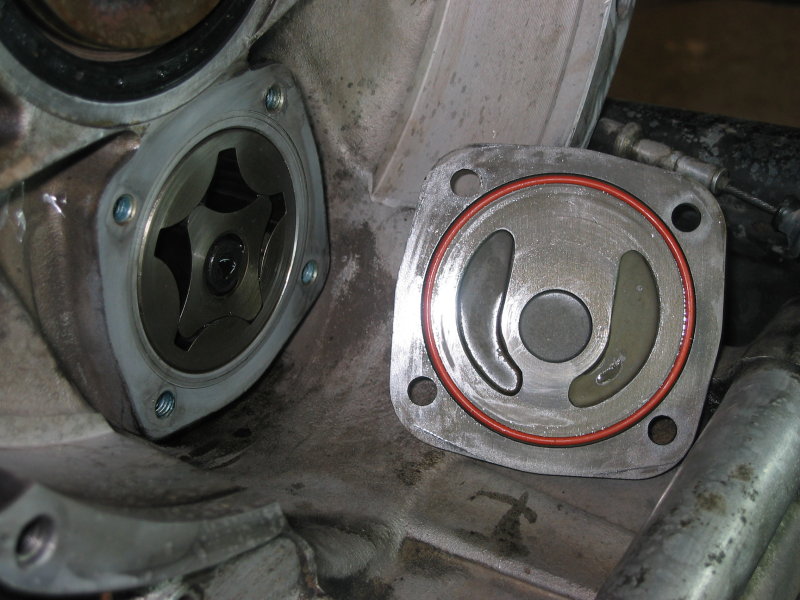
Oil was bubbling out at the front of the oil filter cover - !
I switched the engine off and dropped the bike on the sidestand. I removed the oil filter cover and found all three bolts to be firmly in place and the oil filter as such was also in good shape. The most important item, the white O-Ring (aka "the $2000 O-Ring" since it is a critical part; it must seal both the oil filter tube/canister to the outer cover and the canister to the engine case), also was in the correct shape: slightly compressed. What was it then that caused this leak?
 The question was answered by measuring the distance between the outer edge of the oil filter tube/canister ("Mantelrohr")
and the flat surface of the engine block (see also a Diagram at the HPN website, annotations in German).
In the past, I had always measured something like 3.8 mm here, which is just the perfect distance so that the
white O-Ring is compressed, but no additional shim nor seal is required.
Yet ... the value that I measured now was 4.2 mm. This meant that the tube had settled, the O-Ring with its 4.0 mm diameter
would not seal anymore and oil - as well as oil pressure - was lost.
The question was answered by measuring the distance between the outer edge of the oil filter tube/canister ("Mantelrohr")
and the flat surface of the engine block (see also a Diagram at the HPN website, annotations in German).
In the past, I had always measured something like 3.8 mm here, which is just the perfect distance so that the
white O-Ring is compressed, but no additional shim nor seal is required.
Yet ... the value that I measured now was 4.2 mm. This meant that the tube had settled, the O-Ring with its 4.0 mm diameter
would not seal anymore and oil - as well as oil pressure - was lost.
Technically, the issue could be solved quickly by inserting a suitable shim from an earlier oil change (yes, I keep those ;-) under the cover, just above the (fresh) O-Ring. However, what strikes me is that this movement of the oil filter tube occurred "out of the blue", after more than 140 Mm and 15 years, without any warning. Would I have been on a trip, it was highly probable that the loss of oil - and of oil pressure - would have gone unnoticed until it was too late :-(
My conclusion: Measure the distance described above every time you open the oil filter cover ... and, from time to time, keep an eye on that area to see if it is still dry.
In the 1990s, BMW assembled the GS exhaust system using graphite gaskets. These were soft, easy to install, often reusable and easy to replace.
Later, BMW decided to replace the graphite gaskets by aluminum sleeves. These parts have tight tolerances and require a very clean exhaust system: if you have tightened down the exhaust clamps, they will no longer fit.
This became a problem on my GS after the HPN conversion when the gaskets that I had in stock would no longer fit: now the exhaust had leaks at two transition points. Riding around with unnecessary noise, almost like a "modern" 4V GS with exhaust ... not what I like.
If you're like me, you do not want to buy a special tool to enlarge the exhaust pipes (just for one single use) ... instead, you can use "exhaust assembly paste" (I used the product from Presto). Essentially, you dismantle the exhaust system, clean and degrease all joints and sealant surfaces. Upon reassembly, proceed step by step and apply sufficient amounts of that paste in place of the gaskets, then wipe off excess paste. The paste dries out slowly and the heat from the exhaust gases will finally "bake" the paste into a solid, ceramic-like material.
With that, my GS finally sounds "normal" again :-)
I got my GS in 1990-05, brandnew.
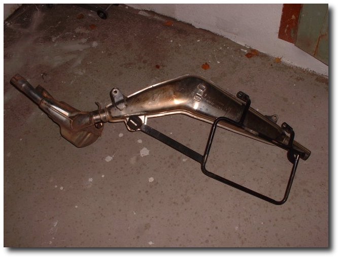
Very early I noticed rusty parts on the exhaust lines. BMW changed these without problems, as they just introduced the stainless-steel exhaust system for the GS. Now I have the stainless steel "end pot", but the collector is still the original version. As it gets hot rather rapidly, there is no real need to change it.
40000 km, changed the two rubber hoses between carburator and cylinder. ID 41 mm, OD 52 mm, length 28 mm.
54850 km (1993-05). Changed the front brake liners. (now Lucas Girling 533, about 35 DM in 1992)
58000 km, 1993-08: Engine rebuild, see above.
61000 km (1993-10): First alternator trouble, see above.
63195 km (1994-01), changed Battery. Now a VARTA, which worked fine until spring 2004. After this time - ten years! - this battery died due to mechanical failure: one of the cells was no longer charged.
65000 km (1994-05): Sudden stop of the engine. It was different from the "must switch to reserve" behaviour - I was riding on the highway and all of a sudden the engine stopped as if someone had flipped the kill switch. First check, does the ignition work? No - no spark. Checked the fuses - OK. Removed the gas tank, and then I saw it: The isolation of two cables (one led to the ignition coil) was worn out, probably doe to vibrations. It took a length of isolating tape (always have a roll of that with you!) and the engine started immediately. I packed everything on the bike and rode on, the final 10 km until I arrived home. - Fortunately this was an unusual situation for a failure: A warm and sunny sunday afternoon, I was not in a hurry, only about 10 km from home, riding on a crowded street (german highway), the next emergency phone was less than 1 km away, and I had lots of time.
68000 km, 1994-06: The replacement alternator is defective, see above.
70100 km (1994-06), changed cables for gas throttle. Cable lengths are: left 1118 mm, right 1158 mm; diameter 1.2 mm, with fixation ("nipple") 6 mm diameter and 6 mm long. These are not identical with the cables of the R100GS (1130 + 1165 mm). (For the clutch, the cable is 1520 mm long with 2.0 mm diameter. One of the "nipples" is 7 mm diameter, the other is difficult to describe ... but it seems that the cable for the clutch is identical for almost all BMW airheads;-)
80000 km, 1995: The engine had starting problems and did not run well. After a long, long search I found that on one of the carbs the spring that holds the "starting carburetor" in its position was used up. The effect was like riding with the choke partially open on one of the carburetors, causing bad response. After changing the spring everything went OK!
86100 km, 1996-06: Changed rear shock, see above.
92100 km, 1997-04: Changed front fork springs, see above.
103900 km, 1999-09: And again, the alternator.
110000 km, 2001-05: Front fork seal (right) defective. Changing the fork seal is actually not very difficult, see above. Almost at the same time, changed the front brake liners - original BMW/Brembo, almost 70 CHF. I still have the impression these are not as effective as the Girling 533. Note: These lasted until 166950 km and had about 2.5 mm left when I changed them.
110500 km, 2001-06: Changed the timing chain.
111600 km, 2001-08: It's the turn of the ignition coil.
114000 km, 2002-05: New seat cover. It was not strictly necessary, but the old one looked shabby. The core is still in perfect shape.
116100 km, 2002-05/06: Gearbox overhaul. At the same occasion, carburetors overhauled (ultrasonic cleaning, new seals and gaskets, new diaphragms).
117900 km, 2002-08: Installed an LED voltage indicator.
119100 km, 2003-04: Verified the alternator brushes and found that they were barely used (2...3 mm missing). - Exchanged one of the H&B bags' mounting brackets (broken part).
124000 km, 2003-07: Minuscule - but annoying - oil leak at the oil pressure switch. Replaced; this requires a 24-mm tubular wrench, which is not part of the stock toolset.
126000 km, 2004-03/04: After ten years, the Varta battery died due to a defective cell. Replaced by a Banner 530.30. At about the same time, I changed the pushrod seals, cleaned the combustion chambers, installed a new shift lever and modified the crankcase venting system. And encountered the slipping clutch syndrome.
130850 km, 2005-05: Changed the final drive.
133500 km, 2005-07: changed the right throttle cable and modified the way these two cables are installed on the bike. I hope that I have finally found a way to remove the permanent strain from the right cable ...
139500 km, 2006-07: replaced the left throttle cable, the carburetor needles (p/n 13 11 1 337 692) and needle jets (p/n 13 11 1 260 971). Shortly afterwards, installed a handlebar riser and lower footpegs.
143400 km, 2006-10: Leaking oil filter cover, due to a settled oil filter tube! Corrected by inserting a metal washer until the expected tolerance was met. - Almost at the same time, the neutral switch of the gearbox started leaking. Replaced in 2007-01.
146400 km, 2007-04: Revised the heads (almost 90000 km after the first revision), due to high oil consumption at rpms above ~4000 rpm. The engine received new valves, valve guides, valve springs etc and the valve seats were re-grinded. Material costs were about 300 EUR.
147000 km, 2007-04: Broken spoke on the rear wheel. Replacement part numbers and prices: 36 31 1 452 737 spoke, 2.30 CHF; 36 31 1 452 727 nipple, 3.10 CHF; 07 11 9 904 003 screw, 0.30 CHF.
148400 km, 2007-07: Following an "unplanned get-off", the bike needed some repair. Replaced the right fork tube, fork brace, lower triple clamp and - while I was at it - steering head bearing, speedometer, control lamps, lamp housing and some worn-out rubber seals. I measured the frame with the BMW tool and found to be perfectly straight and symmetrical, i.e. it had not suffered any damage.
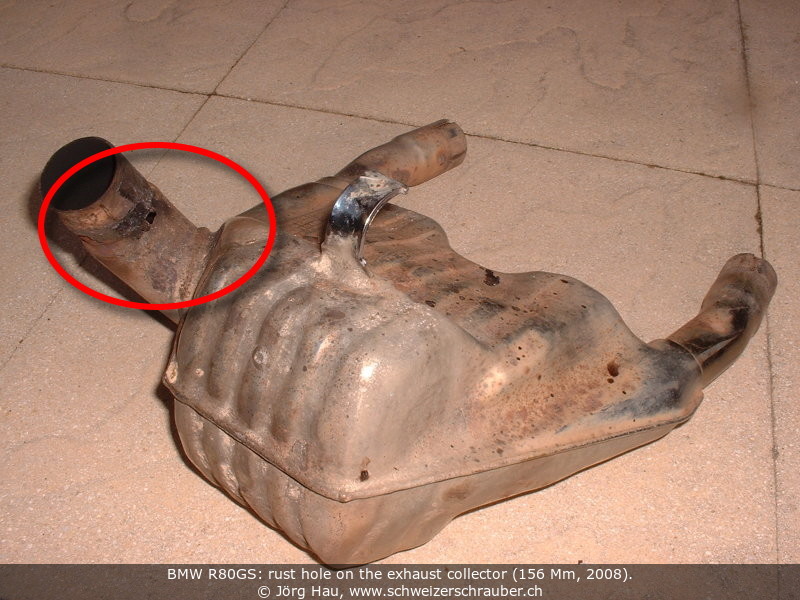
156700 km, 2008-09: The collector box of the exhaust system has developed a rust hole. Swapped against a second-hand replacement that I had acquired a while ago.
158150 km, 2009-04: Repainted the centerstand (got sandblasted in Tunisia 2007 and 2008 ;-) and replaced its worn-out bushings. Changed the leaking rear crankshaft seal and the equally leaking seal of the gearbox entrance. Cleaned and lubed the starter, changed alternator coal brushes.
165800 km, 2010-05: After only 6 years, the Banner battery started to fail. Replaced by a Kung Long WP18-12, a gel-type battery with 18 Ah. At the side of the battery there is now sufficient space for a small box, holding the most common spare parts.
166950 km, 2010-07: The front brake rotor (disc) was worn up. Replaced by a "new old" part (secondhand but 6.0 mm thick, i.e. as good as new) and replaced the brake liners; now using Lucas MCB 533 SV.
168600 km, 2010-10: After a 1500-km trip, the clutch cable started to fail, less than 1 km from my door - that's what I call a trusty steed ;-). This was still the first, factory-installed cable. Replacement p/n 3273 2 324 956, 46.30 CHF.
Summer 2012: Found the source for intermittent charging problems that had bothered me for a while. The insulation of the two cables that lead to the alternator brushes was worn right at the point where these cables touch the engine housing, probably due to vibrations.
180 Mm passed on 2013-08-12 during a gravel trip on the Ligurische Grenzkammstrasse (Route du Marguareis). Nothing particular to report ;-)
190 Mm passed on 2015-05-14 during a trip in eastern Switzerland. Nothing particular to report. I placed order for the HPN frame reinforcement.
194000 km, 2016-06. During a weekend trip in the Aosta Valley, the sidestand attachment of the left crashbar broke. A few km further, the starter motor failed due to dropped magnets. The crashbar was welded a few days later, the starter motor was replaced by a brandnew unit, obtained from Carsten Tiedemann.
197571 km, 2017-06-11. The bike is completely disassembled, the frame sent to HPN for reinforcement and to become HPN 0619. During that time I performed a bunch of maintenance tasks: changed timing chain, replaced alternator wiring, changed pushrod seals, changed all oils, ...
197571 km, 2017-08-20. HPN number 619 is alive :-)
199645 km, 2018-05. The Öhlins shock had developed an oil leak and needed an overhaul.
200 Mm passed on 2019-05-29 during the trip to the HPN Forumstreff 2019. The bike runs fine, nothing particular to report.
202360 km, 2022-05: after 12 years, the Kung Long WP18-12 battery is slowly dying. I replaced it by the same type.
You may be interested to know that the BMW workshop manual for the GS is available as a regular, official part from BMW. The booklet carries part number 01 50 9 799 000 (german version, printed 4.93) and covers the R80GS, R100GS and R100R.
I have been asked a few times what should be considered in particular when you buy a BMW "airhead" GS secondhand. The questions (and answers ;-) have been summarised in a separate document in Adobe pdf format (last updated 2018-07). Feel free to contribute!