Home |
Motorcycle Main page |
Links
This page summarizes some notes and ideas around "batteries" ... lead-acid starter batteries,
as they are used in virtually all motorcycles and cars. If not mentioned otherwise, values are
given for standard, "flooded" 12 V lead-acid batteries.
The usual disclaimer: The procedures and schematics on this page work fine for me,
but if you repeat them, you do everything on your own risk. Battery technology means
sulfuric acid, very high currents, etc., so please make sure that you understand exactly
what all of this is about before you try anything. When in doubt about some specific values,
consult the datasheet for your battery.
Testing a lead-acid battery:
Voltage |
Acid density |
Capacity |
Impedance
Charging a battery:
Charging modes |
Voltages
Improving a simple battery charger:
Design goals |
Circuit description |
Construction
Summary
There are several ways to assess the condition of a lead-acid starter battery, from a
simple inspection with a voltmeter up to load testing. For those of you that are in a hurry,
a rule of thumb is "terminal voltage 12.5 V or higher and density in all six cells
1.24 g/ml or higher means that the battery is probably in good shape".
A fully charged 12-volt lead-acid battery has a voltage of 12.6...12.8 V at 20 °C.
The exact terminal value will depend on the individual construction, in particular the alloy of the
electrodes - Pb, Sb, Sn, Ca - and the concentration of the acid used. The voltage for sealed
lead-acid batteries - SLA - is usually at the upper end of this range.
On the other hand, a battery is considered discharged if the voltage reaches 11.6...11.7 V (same for SLA).
In this state, the battery will still be able to deliver quite some current, however, the voltage
will drop rapidly - i.e. the "internal resistance" is very high. If you don't recharge in this state,
the battery "sulfates" and this will affect its performance.
Thus, one of the simplest approaches to determine the charge state is the
open-circuit voltage of the battery:
- First remove the "surface charge" that builds up on the plates - if you do not remove the surface charge,
you will measure values that are somewhat higher and thus falsify the result. For car batteries,
the usual procedure is to either turn the headlights on for 3 min, or to crank the engine for some
10 s (this draws some 100 A). For a motorcycle, I suggest to leave ignition and
headlight on for about 1...2 minutes (depending on its battery size).
- Then, use a good (read: accurate, calibrated) digital voltmeter and measure the voltage at the
battery poles.
- 12.6 V or better (at 20 °C) is fully charged - every 0.2 V less means roughly
25% less capacity. Thus, 12.2 V is only 50% charged and 11.8 V or less is an empty battery.
- For SLA, use an upper value of 12.8 V and count approximately 0.25 V per 25% step.
If the measurement above leads you to suspect trouble - and especially when the battery failed within
a very short time -, use a hydrometer to determine acid density ("specific gravity") of the acid in all six
cells. Fresh battery acid is sulfuric acid with a density of 1.28 g/ml (38%, ca. 4.9 mol/l).
Warning: Sulfuric acid is a nasty compound: handle with great care, wear protective clothing and remove
splashes with lots of cold water!
- To be in good shape, density should be above 1.24 g/ml (33%, 4.1 mol/l) in all cells.
With an old battery that has already undergone a certain degree of sulfation, you may find yourself
still operational with 1.20 g/ml (28%, 3.4 mol/l).
- In any case, the deviation between the individual cells must be less than 0.05 g/ml.
If one cell shows a very low acid density that does not improve after charging, you can safely suspect
that it is defective - most probably such a battery will self-discharge within one week.
Battery capacity can be measured by discharging a fully charged battery with a known
load and measuring the time until a pre-set voltage (11.8 V) is reached.
Usually, battery capacity is measured at a discharge rate of 0.05 C. The capacity is,
however, not constant: the slower the discharging rate, the higher is the capacity that is
available from the battery. Vice versa, a higher discharge rate will lead to a slightly lower
capacity reading.
However, it should be noticed that deep discharging a battery at high rates for a short time
is not as severe as deep discharging the same battery at low rates over a long time.
In particular, emptying a battery below ca. 11.6 V and then letting it sit there is
dangerous, as the battery will sulfate.
Another parameter that can be determined is the impedance of the battery, i.e. its internal resistance.
A healthy, fully charged 12 V battery will have an internal resistance in the 10...30 mΩ
(yes, milliOhm) range. This value increases with age and degree of sulfation.
To determine the impedance of a battery, usually its terminal voltage is measured while a significant current
is drawn from the battery. However, it is not necessary to draw a huge current pulse - already a
1 Ω resistor gives sufficient load. The voltage drop is easy to measure with a digital
voltmeter, you just have to be quick.
With the following technique, I obtained identical results (within a few mΩ) using both a
1 Ω and a 0.2 Ω load - yet the latter will draw more than 50 A and
produce more than 500 W of heat.
- Connect an accurate digital voltmeter directly to the battery poles.
- Connect a precisely known load (e.g. 1 Ω 1% 20+ W ceramic resistor)
across the battery and quickly (!) measure its terminal voltage under this condition, U1.
- Warning: the current will exceed 10 A, so use appropriate cables and connectors.
- Warning: The power dissipated in the resistor is very high - for a 1 Ω resistor,
this is more than 150 W! The resistor will heat up very quickly, which
in turn will falsify the voltage readings - so conduct the whole measurement within
max. 5 s and don't hold the resistor in your hands ;-)
- Disconnect the load, wait about 1...2 min for the voltage to stabilise and determine
the terminal voltage without load, U2. I do the measurement is this sequence, as the current
pulse in the previous step will remove any surface charges. Thus, here you will get the "real"
terminal voltage without load.
- The internal resistance is then calculated according to Ohm's law, R=U/I, where U is the
voltage difference U2-U1 and I is the current (which, in turn, calculates as I=U1/R).
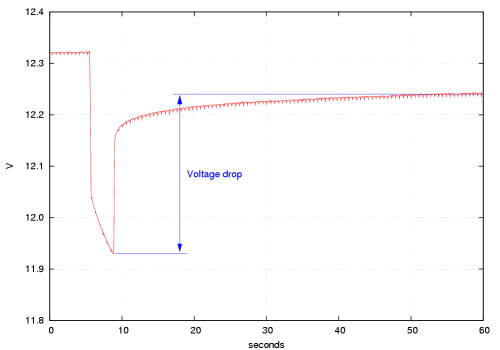
As an example, with one of my motorcycle batteries I measured 12.31 V with a
1 Ω load and 12.74 V without load. The current drawn during the measurement
calculates as 12.31 A and with the voltage drop of 0.43 V the internal resistance
is 0.43 V/12.31 A = 0.035 Ω or 35 mΩ.
Not too bad for a 10-year old 25-Ah battery ...
A two-year old battery of the same size gave 11.93 and 12.24 V, respectively,
corresponding to 26 mΩ. This measurement is shown in the diagram above.
On the other hand, a battery with a defective cell will show a much higher impedance.
I had such as battery where the open-circuit voltage of 12.15 V was still acceptable,
but with a 1-Ω load the voltage dropped to 10.96 V. The internal resistance is more
than 100 mΩ!
Why?
An automotive battery is built for cyclic use, i.e. charging and discharging. Actually this is
exactly what happens when you use your motorcycle or car: the electric starter draws current,
and during the following ride the alternator will then re-charge the battery. Under normal conditions,
the alternator provides all of the electrical current that is required by the vehicle. The battery is
required only for starting (hence the name "starter battery") and eventually as a buffer when the
alternator does not supply enough voltage (e.g. in slow traffic).
Correct charging of a battery is essential in optimising battery performance and life: always
recharge a battery immediately after discharging. To charge a battery, the external voltage must
be higher than battery voltage (... pretty obvious, no?). However, if the applied voltage
exceeds a certain limit, the acid will start to decompose by electrolysis, a process that is
commonly but incorrectly referred to as "boiling", due to the appearance of gas bubbles.
Depending on its primary application, two basic categories of battery charging exist:
so-called cyclic charging (max. 14.7 V) and float charging (13.5...13.8 V).
Cyclic charging is meant for applications where the battery is repeatedly discharged
then charged, e.g. portable equipment, wheel chairs, golf carts etc.
Float charging applies to applications such as emergency power supplies.
Automotive use lies just between these two modes and most chargers indeed apply a
mixture of the two modes. In practice, up to four (!) different cycles may be used:
- When the battery is considerably discharged, the first step is bulk charging up to 80% of the
battery capacity, allowing the battery to absorb a large amount of charge in a short time. A
lead-acid battery can accept a higher rate of charge when it is partially depleted than when
its near full charge and consequently, a rather high current is used in this mode
(but not more than 10% of the nominal battery capacity, i.e. 2.5 A for a 25-Ah battery).
- When the battery voltage reaches about 14.4 V, the absorption charge stage begins.
Here, voltage is held constant (14.4 V) and the current decreases over time as the battery
takes up charge. This continues up to ca. 98% charge. At this point, the current drops to something
like 0.01 C (250 mA for a healthy 25-Ah battery).
- At this point, some - very few - chargers briefly apply an equalizing charge; this step
is apparently useful to equalize voltage in all cells. For SLA, the voltage is set at +5% (15.6...16.3 V).
- What follows is float charging: in this state, a constant voltage of not more than 13.65 V
is applied, resulting in a low current. Over time, this will bring the battery to 100% charge and it will
maintain it at that state. This voltage that is just sufficient to keep it from discharging but insufficient
to cause overcharging.
The charging voltages vary only very slightly between standard and sealed lead-acid
batteries; for the latter, the cyclic charging voltage is usually about 500 mV higher,
while the float voltage is the same. Some examples with data from the manufacturer's datasheets
(the original references have disappeared from the web so I removed the links):
| Type |
Cyclic voltage |
Float voltage |
Equalizing voltage |
| Varta, flooded lead-acid (general) |
IU charger with 14.1...14.4 V and max. 0.1 C as charging current. |
13.6...13.7 V |
Up to 16 V, max. 0.1 C current and for less than 5 h.
Not more than once per year (water consumption). |
| Fiamm FG21803 (SLA, but not for automotive use) |
14.4...15.0 V |
13.5...13.8 V |
n/a |
| Odyssey ("dry cell" SLA) |
14.4...14.7 V |
13.6...13.8 V |
n/a |
Ideally, the float voltage should be temperature compensated (at least above 25°C). The exact value
depends again on the manufacturer, but is generally between -2 mV and -6 mV per cell
and per K, with a steeper coefficient for cyclic use.
As an example, FIAMM specifies for its above-mentioned SLA battery a temperature coefficient
of -18 mV/K for float charge and -30 mV/K for fast "cyclic" charge.
So, when in doubt, look up the datasheet for your individual battery!
You can also charge a battery purely by float charging, although this will take more time.
Just set a regulated power supply ("laboratory supply") to 13.65 V, adjust the current
limit to match your battery and connect. The charging process will first be current controlled,
then voltage controlled.
- YUASA Technical Manual (pdf).
- Powersonic. Technical handbook sealed lead-acid batteries (pdf).
- An accurate and concise description of battery technology, with lots of diagrams, can be found at
taunus-biker.de (in German).
Most low-cost battery chargers will not necessarily regulate the charging voltage nor current.
Usually, those units consist merely of a transformer with a rectifier, providing a pulsating DC current.
While the average voltage under load is somewhat like 13...14 V, under high load this voltage
decreases and under weak load it increases ... leading to far more than 14 V at the battery and
the infamous "boiling" when it reaches the end of the charging cycle. Thus, these chargers provide
short charging times, but it is required to disconnect them at the end of the charging process.
I had such a charger myself and wanted to modify it so that it
could be left hooked up to the battery, without said need to disconnect it after a given time.
There are many circuit diagrams available that describe home-made battery chargers.
However, almost all of those use a high-quality transformer, providing at least 18 V
at the input of the regulating circuit. Which is not what I was looking for: I already had
transformer, rectifier and casing, but the above-mentioned "soft" characteristics of the transformer
did not allow the use of a conventional voltage regulator circuit. All that I needed was a circuit
to provide overvoltage protection to the battery - if possible, using standard parts that I had at hand.
The resulting circuit is shown below. It is inspired by a similar, low-power circuit from
www.techlib.com.
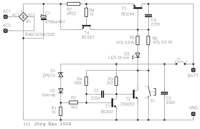
The basic design is pretty much the same as in the automotive voltage regulator, described
elsewhere on this website: As long as the input voltage is low,
D1 is not conductive, so T1 is turned off. In this state, T2 is hooked up to the positive
battery line via R3 and is conductive: current flows through R5 and the LED (as well as
through R6, see below), opening T3.
When the voltage across the battery is high enough to bring D1 in its conductive state,
T1 will also become conductive and will connect the base of T2 against the negative line.
T2 will close, the current through the power transistor is reduced, the battery voltage drops
and the cycle repeats. You get the idea.
This charging process is less effective than the unmodified charger, as the battery is only charged
"by pulses". However, the advantage is that the battery is effectively prevented from overcharging.
Safety. A special feature is that the output will remain switched off until a battery
is connected. As soon as the battery is disconnected, the output voltage is switched off again.
Caveat: This means that you will not be able to recharge a deep-discharged battery without
an auxiliary voltage. In this case, press the pushbutton S1 (a normally-open type) a few seconds
to start the charger. - Make sure not to press the button for a longer time since it effectively bypasses the overcurrent limiter (described below).
Output stage. An early prototype of this circuit used a
complementary Darlington transistor as output stage. However, an inherent problem of
any bipolar Darlington transistor is that the voltage drop across the CE connection is at
least 0.8 V. This was too much for the present application, where the voltage of the
transformer under load was already quite low. The solution - apart from a relais - is to use a
single transistor instead of a Darlington and to drive it almost into saturation
so that the voltage drop across CE is as low as possible.
The data sheet of the BD244 tells us that we can expect a current gain of approx. 90, so a
base current of 20 mA - the LED - should be sufficient to drive about 2 A of current.
Under this condition we still have a voltage drop of 0.3 V across CE ... which
can be reduced further by increasing the base current, which is the purpose of R6.
Current limiter. The commercial charger that I had was equipped with an electromechanical
3-A "fuse" that refused to interrupt even after several seconds of short-circuit testing ...
so it was mandatory to add an electronic current limitation. This is formed by T4 and R7:
as soon as the voltage drop across R7 is large enough to open T4, the latter will shorten
out the BE-junction of T3 and cut the output off. This circuit is very fast and provides the
additional advantage that it avoids the initial "current spike" that frequently occurs when a charger
is first connected to the battery. You can use this circuit to charge your motorcycle's battery via
the auxiliary plug and even use the electric starter, without the risk of blowing the fuse.
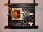
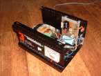
Looking at the harsh conditions under which many battery chargers are used (dust, humidity),
you will want to make sure that the circuitry is build up rather rugged, on good PCB material,
and probably sealed with plastic spray after testing. My prototype
was built into an old EINHELL "hanseatic" 3-A charger, which showed an idle voltage of 14.5 Veff.
On the back of the case I added a pair of 4-mm connectors to allow the use of standard laboratory cables,
and the pushbutton switch just below.
The upper switching voltage of the circuit is basically determined by the voltage drop across
D1 and D2, plus the base-emitter-voltage of T1. With D1 a ZPD13 and D2 a Si diode, the voltage should
be 14.2 V. However, I have come across Zener diodes with deviations as large as 0.7 V from the
nominal value, so you may want to determine the real Zener voltage before you actually solder it in place -
the "target value" of the circuit is 14.2...14.4 V.
Additional diode(s) in series with D2 may be used for such fine-tuning, but can also be wired (using a
switch across the diode) to provide an alternative voltage setting.
The lower switching voltage is determined by said upper voltage, minus by the hysteresis
caused by R4. With 180 kΩ as shown in the circuit diagram, hysteresis is about 0.8 V,
which means that the circuit will switch off at 14.4 V and back on when the voltage reaches
13.6 V. Thus, the circuit will visibly (LED) switch on and off while the battery approaches full charge,
and finally "settle" at around 13.6 V battery voltage.
The exact hysteresis and switching voltage depend on the current gain of T1 as well as on R1, R2 and R4.
A high β of T1 will require a higher R4, but if R4 is increased to e.g. 270 kΩ, the hysteresis
window is only 0.3 V. This means in turn that you will now need to reduce the upper limit to prevent
overcharging, as the lower voltage limit is now only 0.3 V below the upper limit ...
Most other items are not critical and are given in the circuit diagram. Capacitors C2, C3 and C4 stabilise the
circuit; 47 nF to 470 nF should do the job. T3 is to be mounted on a small heat sink, albeit
it will not get very hot: In contrast to common voltage regulator circuits, this power transistor is not used as a
variable resistance but only in switching mode (on or off), so power dissipation depends mainly on the the
C/E voltage in conductive state and on the actual current.
The feedback line from the battery to D1 and R3 should be brought as close as possible to the battery
(hence the jumper symbol in the circuit diagram).
On the PCB I provided the connections for a standard bridge rectifier (B1), although my prototype
uses the rectifier that came with the charger (in spite of their voltage drop, which can be as much
as 1.8 V at 2 A). - C1 should have some 1...2 mF per A of charging current.
This information is provided in the spirit of "open design". The concept is
similar to that of open source software: It is available in "source form". Here,
this means that I am making the design information freely available and you
may use this information to build your own systems for personal use, free of
charge. However, if you wish to develop some commercial product based on the
information provided here, I require that you seek a licence from me first.
There are many commercial and home-made battery charger circuits on the web,
and I do not have the intention to provide a complete inventory ;-). The following links
describe some circuits that I found particularly interesting:


